With a budget of less than $250, you too can build your own BoardBot. With open source CAD and and code, you can remix your BoardBot to fit your exact needs.
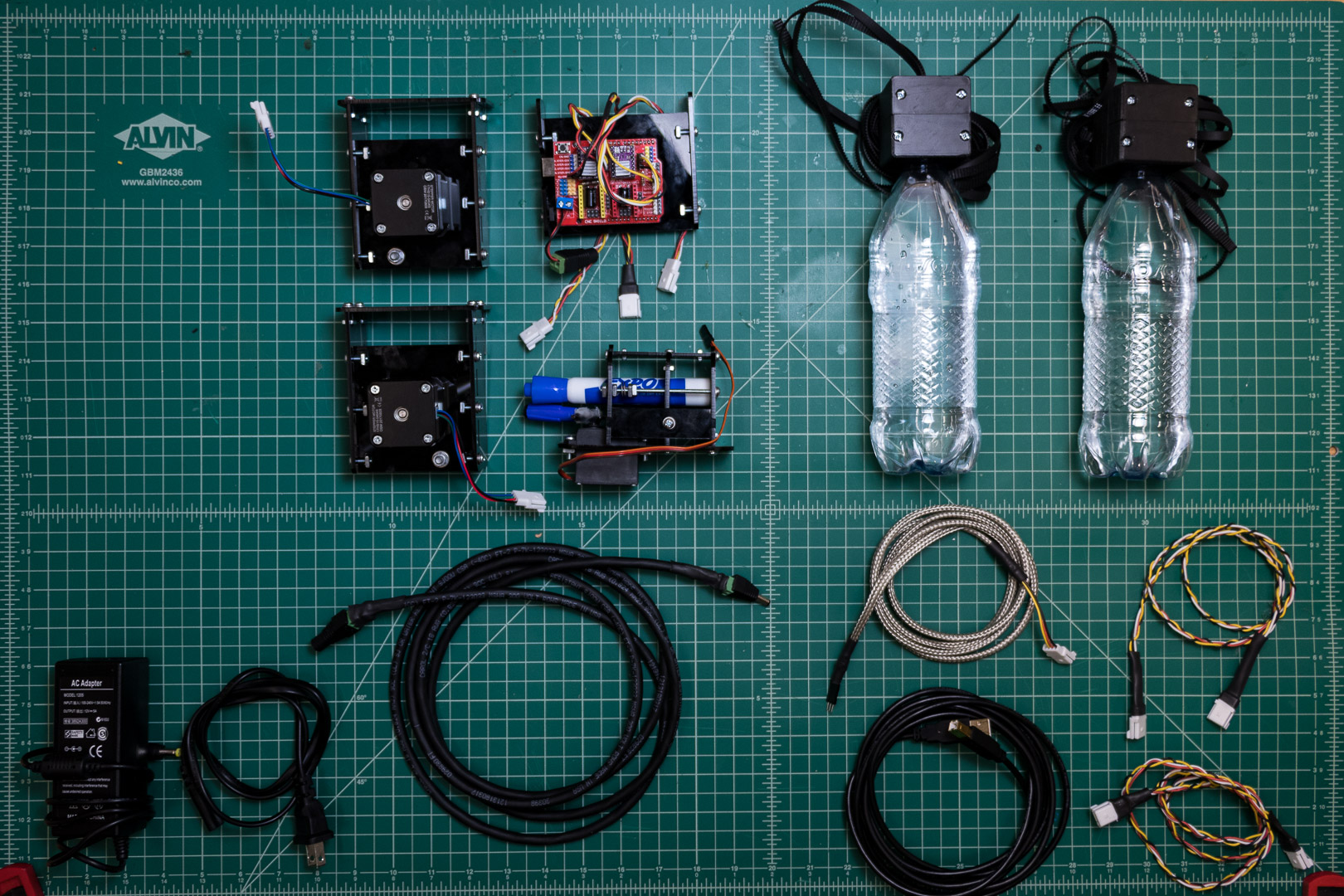
BOM
| Name | Description | Cost (USD) | Source |
|---|---|---|---|
| Acrylic | Approximately 12”x24” | 15 | Buy |
| Stepper Motors | Two Nema 17 Bipolar | 2x 10 | Buy |
| Stepper Motor Driver | CNC shield with 4x DRV8825 | 15 | Buy |
| Arduino Uno | 10 | Buy | |
| Servo | Standard hobby grade | 10 | Buy |
| USB Cable | 10ft Type A to B | 5 | Buy |
| Timing belt and Pulleys | 10m GT2 belt, 2x pulleys | 10 | Buy |
| Idlers | 2x Idlers | 5 | Buy |
| General Screws | #6-32 1/2” (>20 count) | 3 | Buy |
| Nuts | Square #6-32 (>20 count) | 3 | † Buy |
| Washers | #6 (>20 count) | 1 | † Buy |
| Metric Screws | Two m5x30mm | 1 | † Buy |
| Metric Nuts | Two m5 | 1 | † Buy |
| Long screws | Two #6-32 x 2” | 1 | † Buy |
| Total | 90 |
† indicates brick and mortar purchase recommended, for cheaper low-volume pricing.
Our mechanical design is available on Onshape.
Our software is available on GitHub.
Build Instructions:
Laser Cutting
For laser cutting fabrication, you will need:
- 12”x24” 1/8” Acrylic sheet
- Laser Cutter (Capable of cutting acrylic)
A cut sheet is available Here
Download sheet as whatever format is convenient for your Laser Cutting toolchain, and cut all paths.
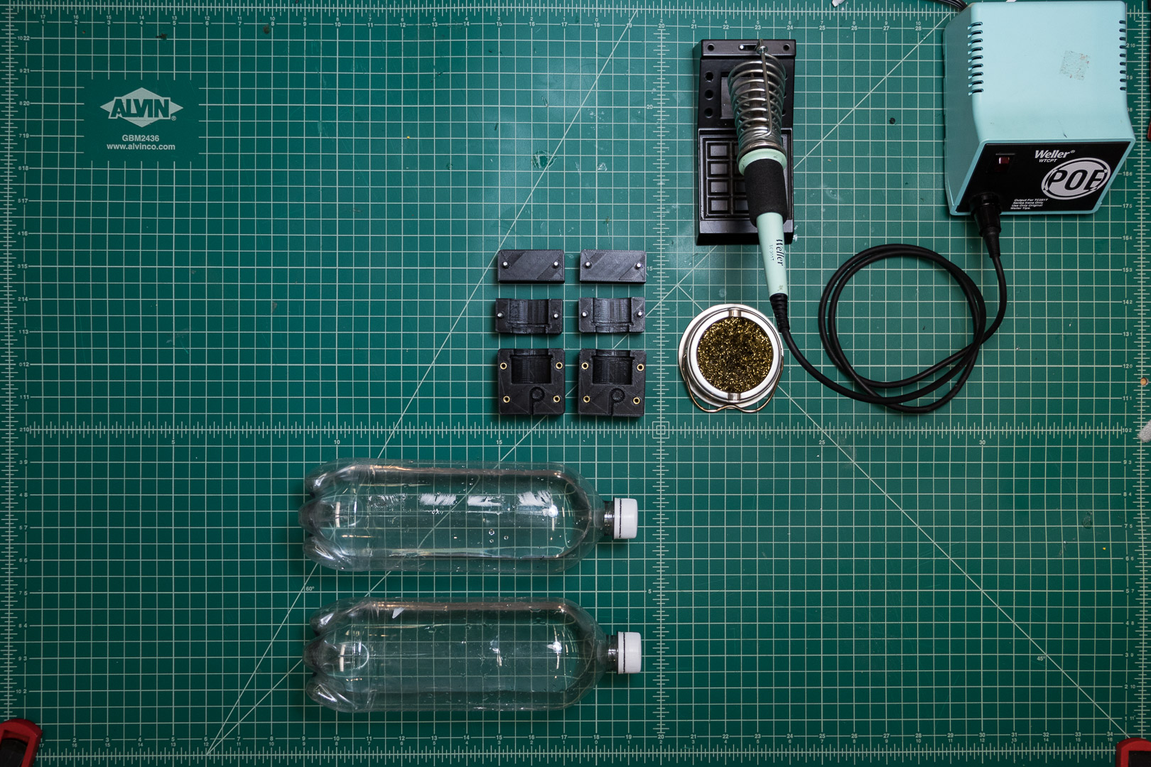
Counterweights
3D printing
For this fabrication, you will need:
- 3D Printer
- ~100g of Filament
Parts are available Here
Download as STL, and print two copies of each part.
Assembly
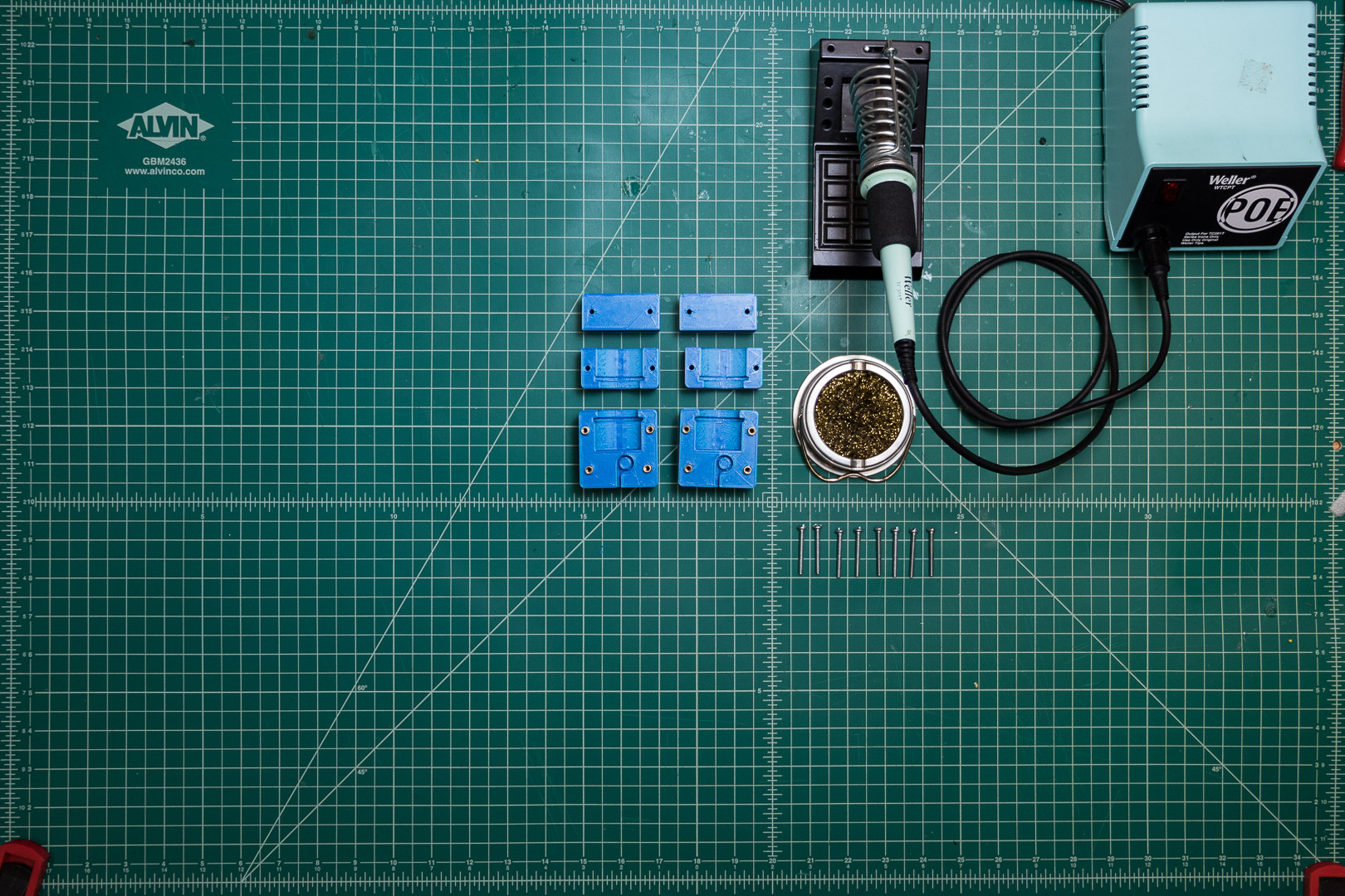 For each counterweight assembly, you will need:
- Back block
- Belt cover block
- Bottle cover block
- 4x #6-32 heat set inserts
- 4x #6-32 1 1/4” screws
- Bottle
- Soldering iron
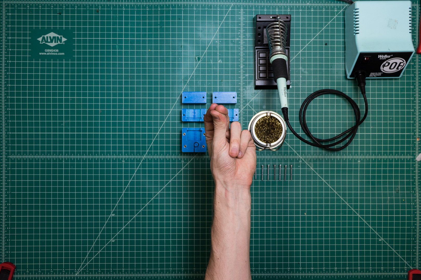
Place each heat set insert in the corresponding hole in the back block, then use the soldering iron to gently push them into place.
Make sure your prints match the color of your build.
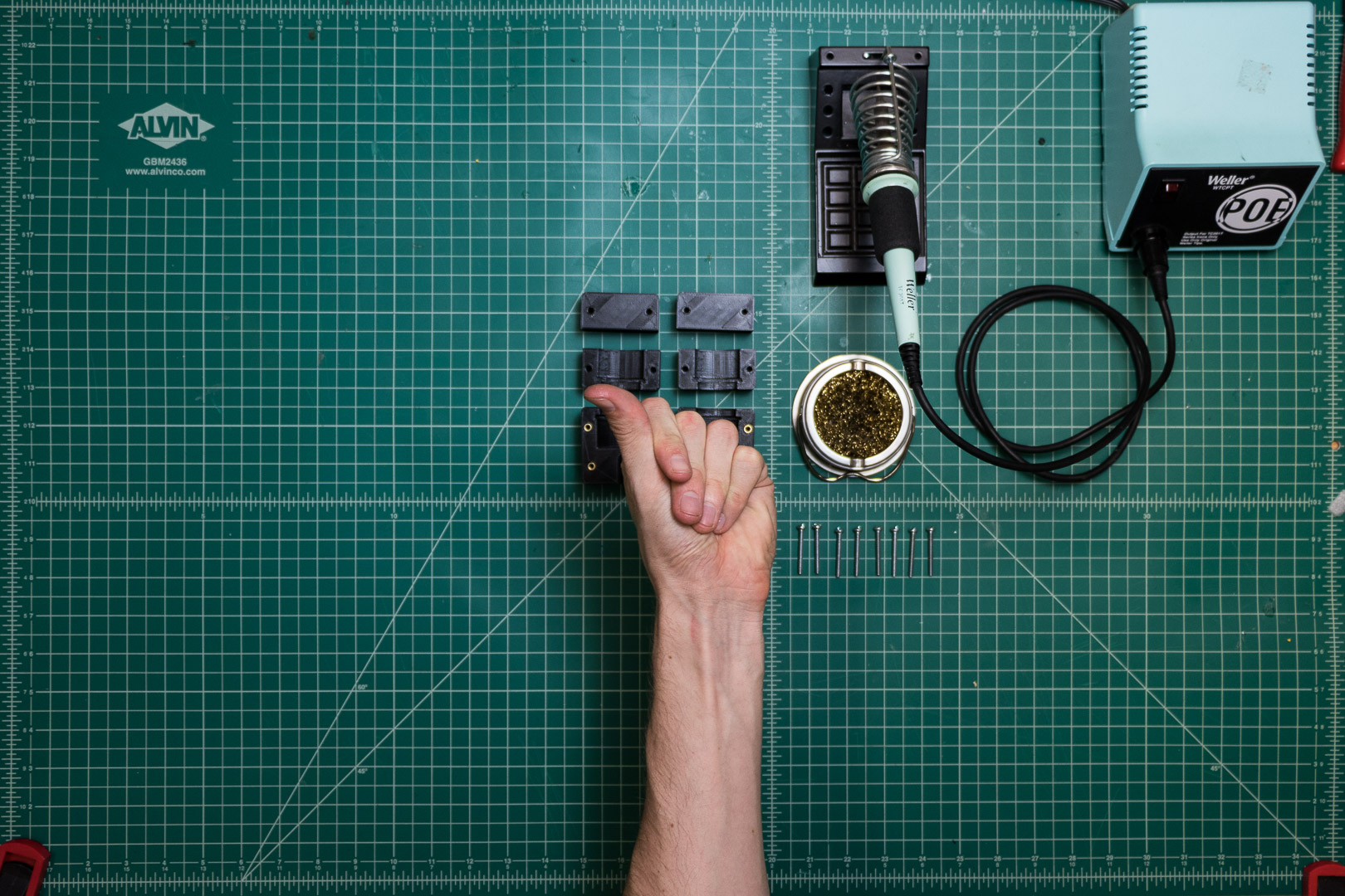
Snap the bottle into the bottom of the back block.
After final assembly, screw the cover blocks on.
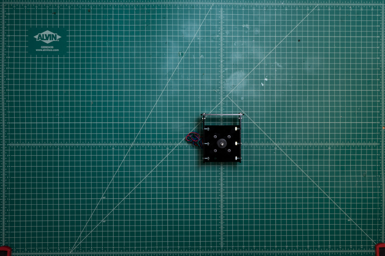
Stepper Mount
Chassis
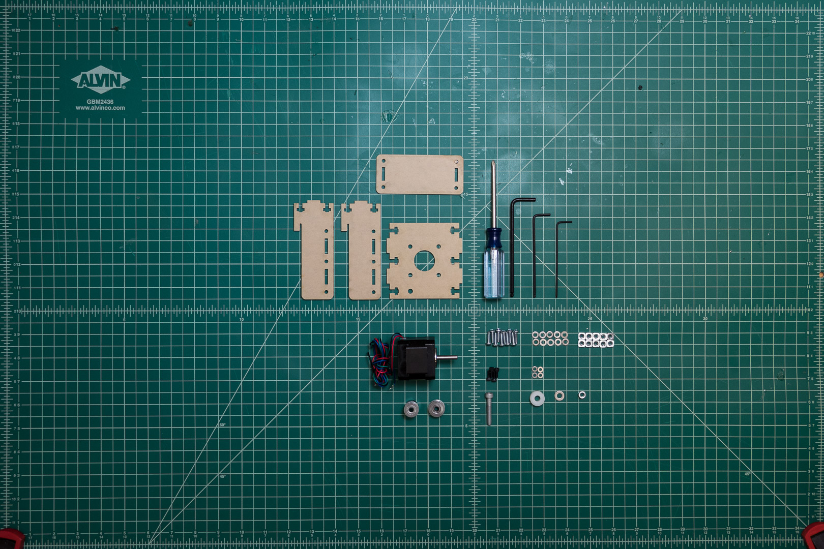
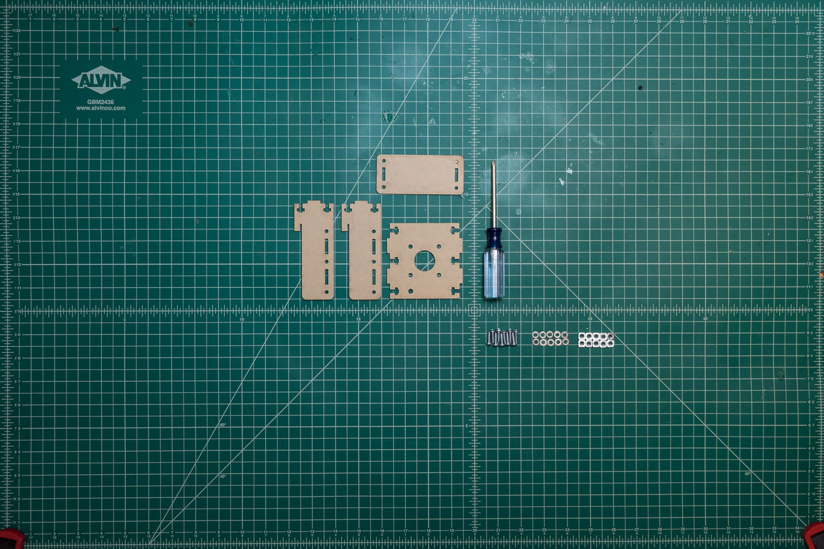 For each stepper mount, you will need:
- 10x #6-32 1/2” screws
- 10x #6-32 square nuts
- 10x #6 washers
- 2x side panels
- Mount panel
- Top panel
- Phillips Screwdriver
Take care to reverse the chirality of the mount panel for the second stepper mount.
Hardware
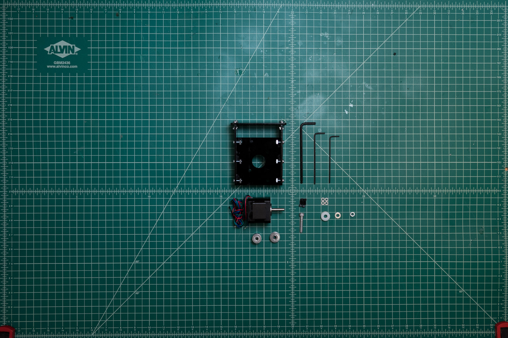 For each stepper mount, you will need:
- NEMA 17 stepper motor
- 4x M3-8mm screws
- 4x M3 washers
- M5-30mm screw
- M5 nut
- M5-10mm spacer
- M2 hex key
- M2.5 hex key
- M4 hex key
Take care to align the direction of the wire exit from the motor with the direction of the idler pulley.

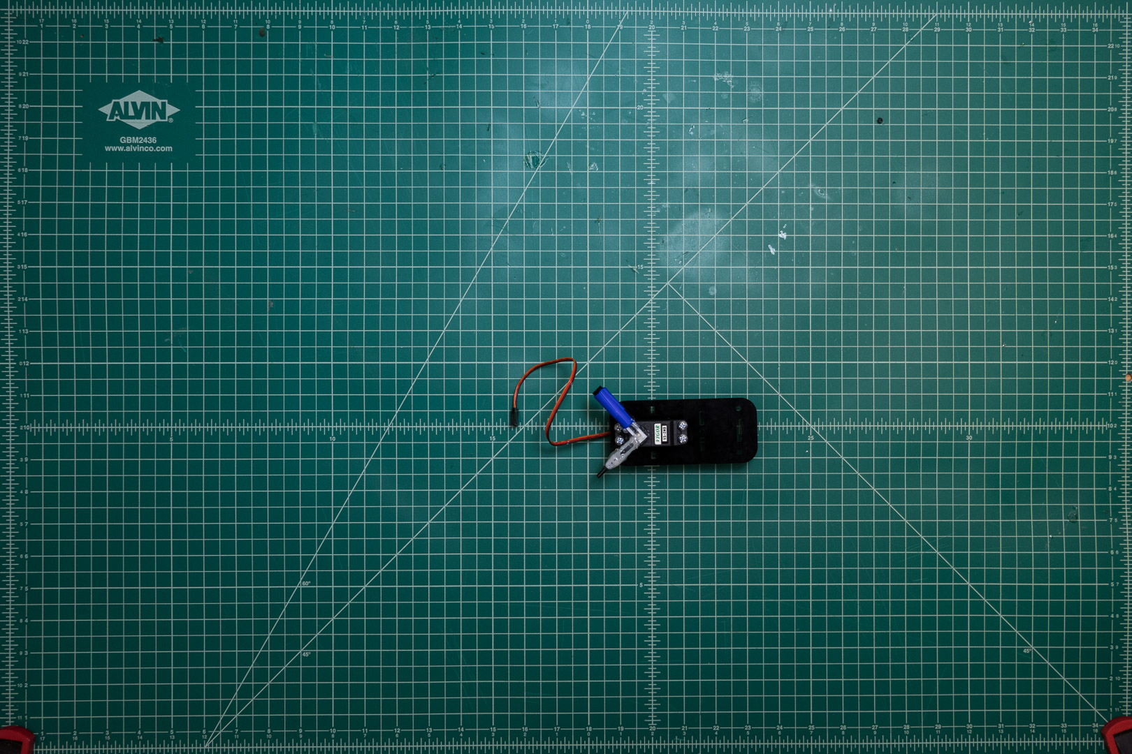
Tool Changer
Chassis
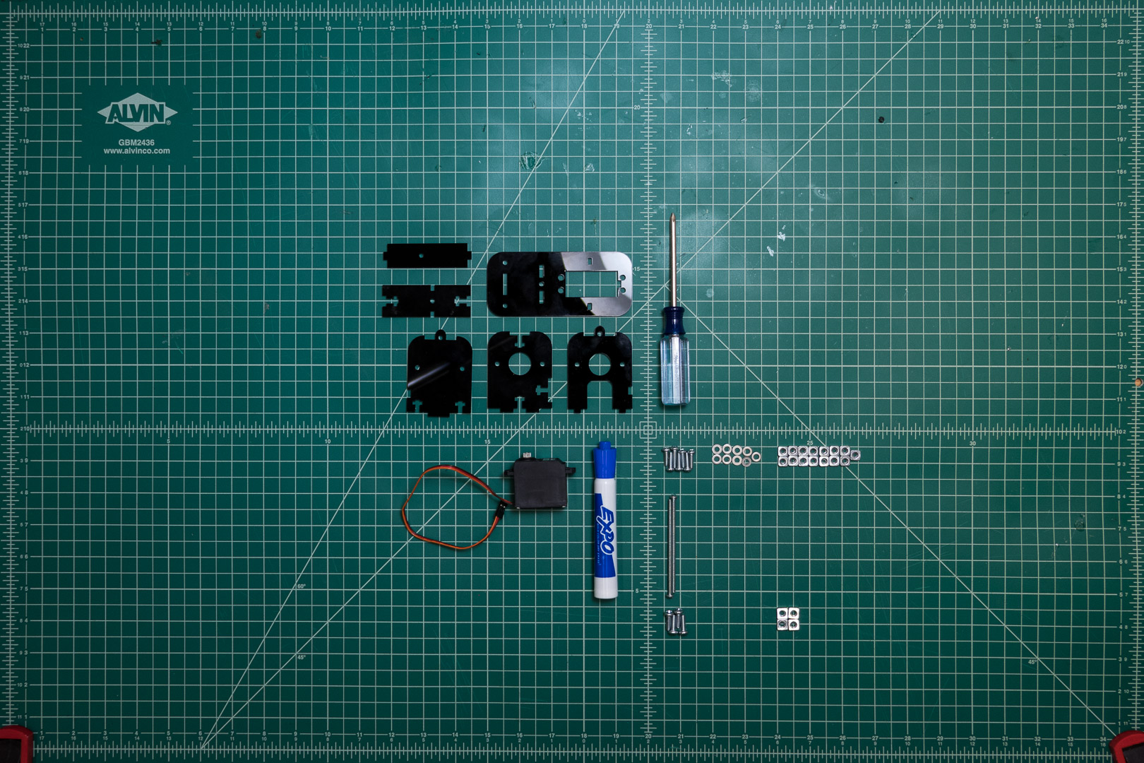 For the Tool Changer, you will need:
- 7x #6-32 1/2” screws
- 15x #6-32 square nuts
- 7x #6 washers
- 2x #6-32 2” screws
- 4x #8-32 screws
- 4x #8-32 square nuts
- Base plate
- End plate
- Mid plate
- Front plate
- Top plate
- Side plate
- Whiteboard marker
- Hobby servo
- Phillips screwdriver
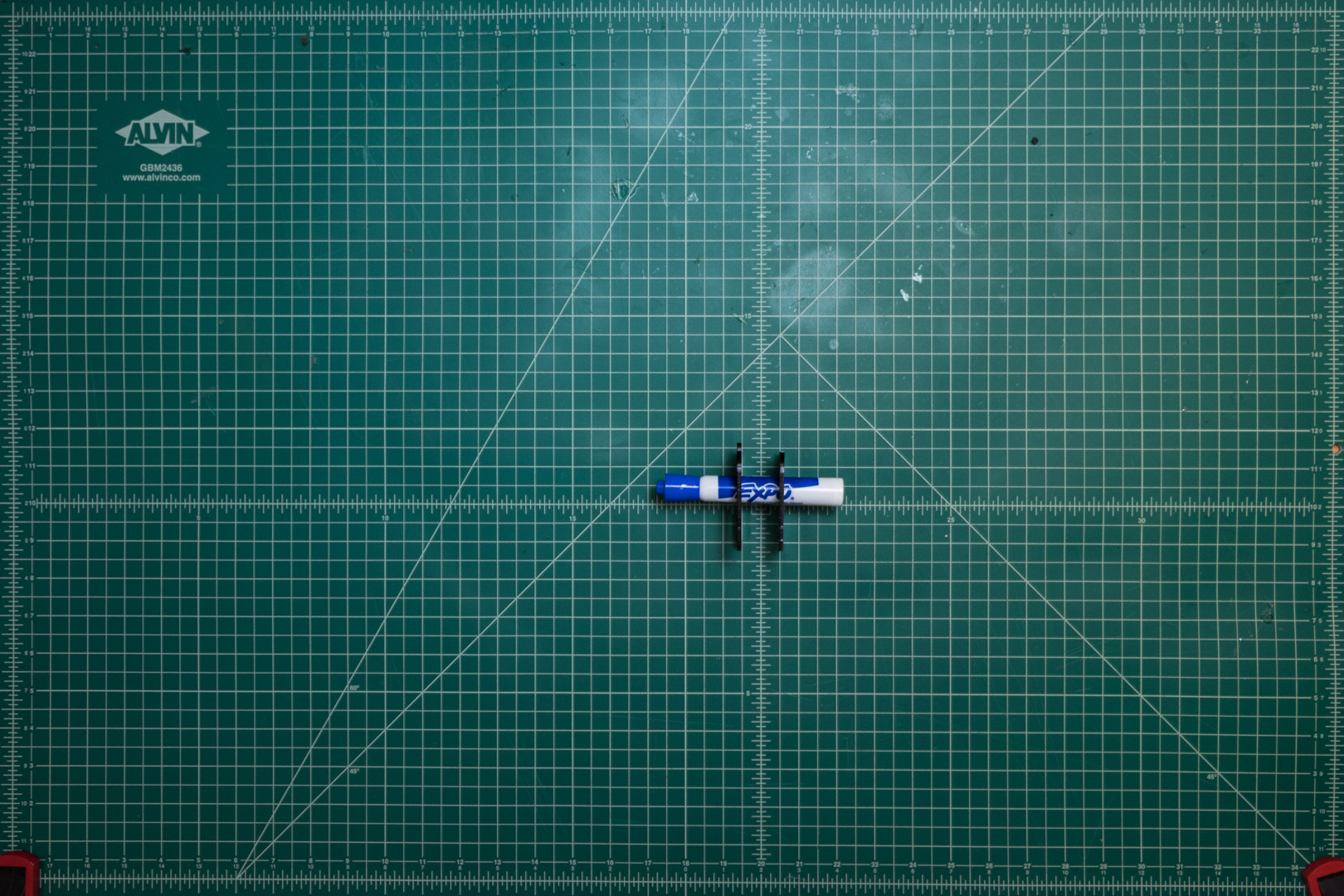
First, uncap the pen, insert through the mid plate and front plate, then recap.
 Next, install the servo in the base plate with the #8 fasteners.
Assemble the rest of the chassis, taking care that all the side plate notches are on the same side.
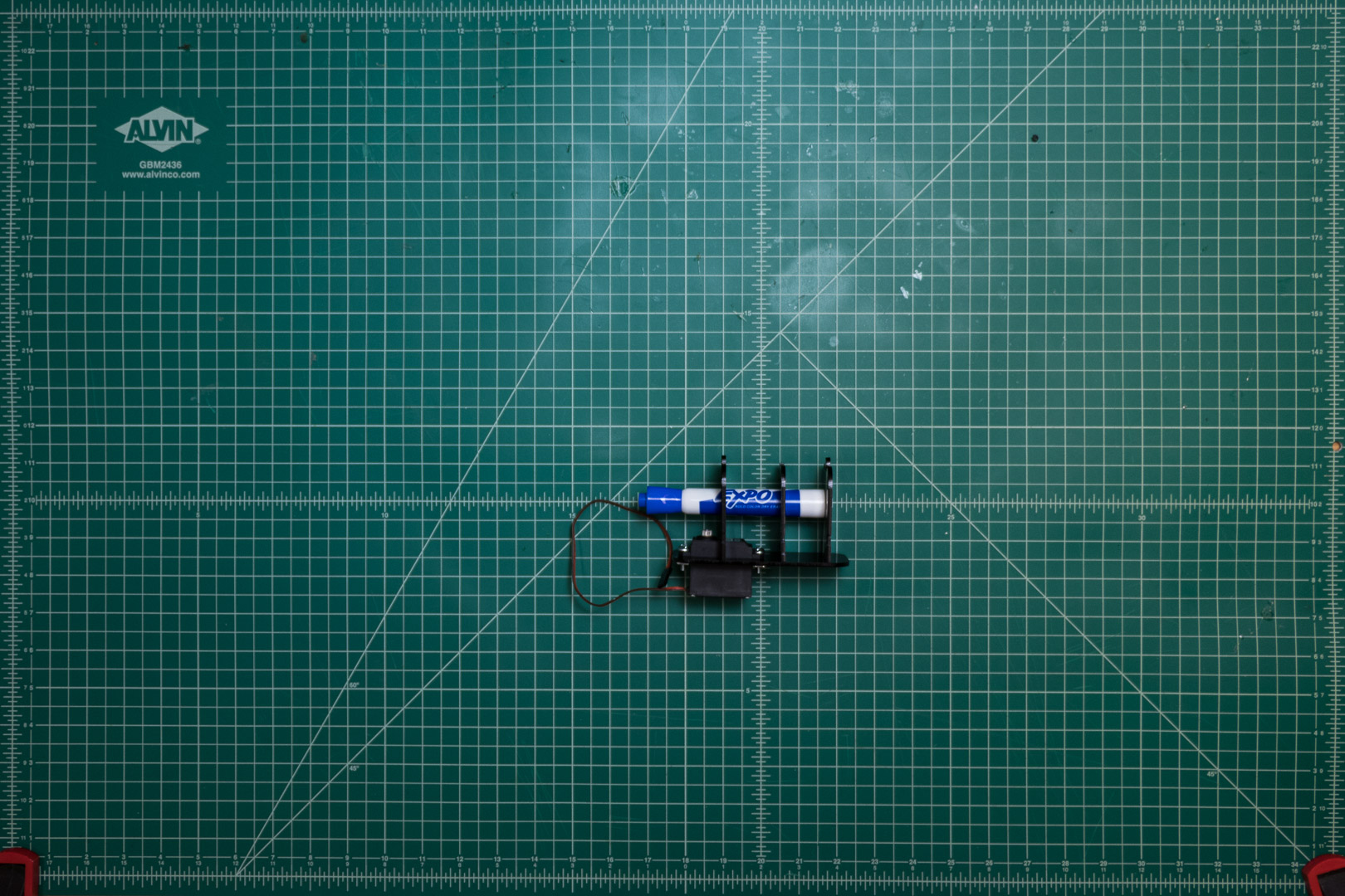
Run the 2” #6 screws through the sides of the tool changer, adding 4 nuts in the middle of the screw. These will serve as the adjustable contact point for the belts.
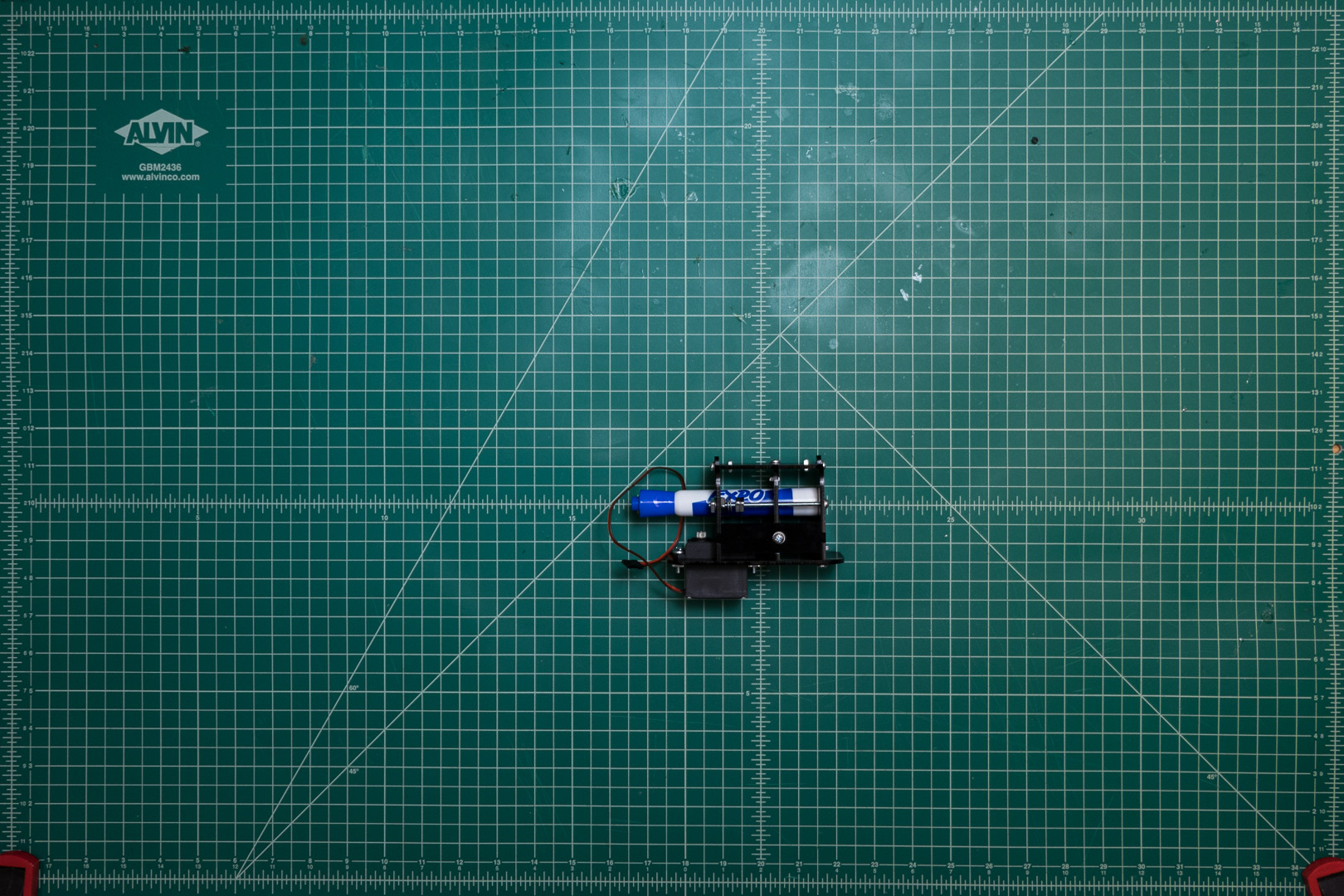
End Effector
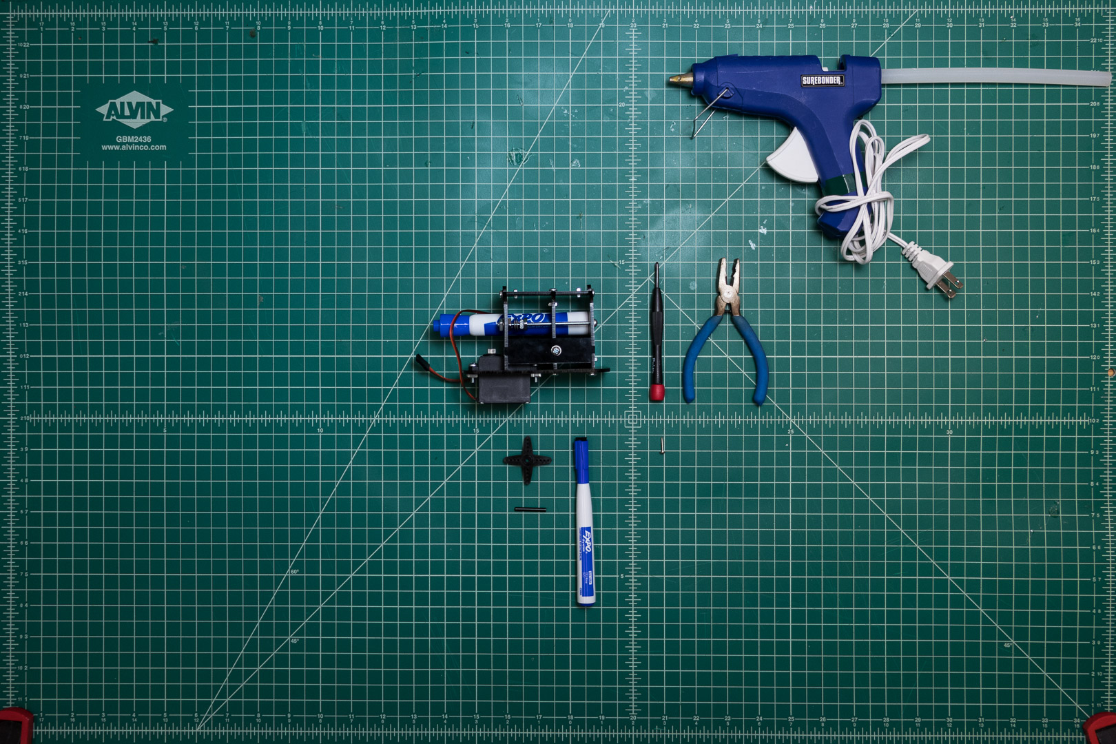 For the End Effector, you will need:
- Assembled Tool Changer Chassis
- 4-way servo horn
- Servo horn screw
- 1” pin
- Marker with eraser cap
- Hot glue gun
- Cutting Tool
First, cut two of the lobes off of the servo horn.
 Next, hot glue the pin and the marker cap to the remaining two lobes
 Finally, install the servo horn on the Tool Changer Chassis.
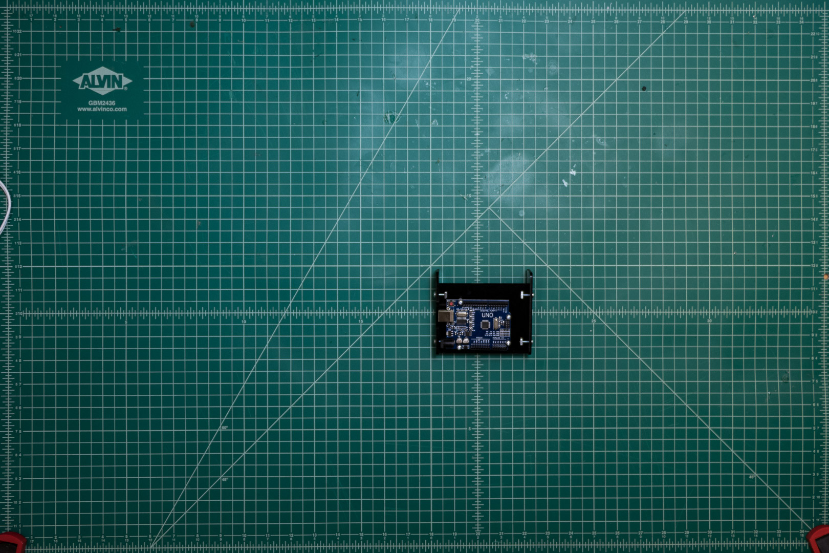
Microcontroller Mount
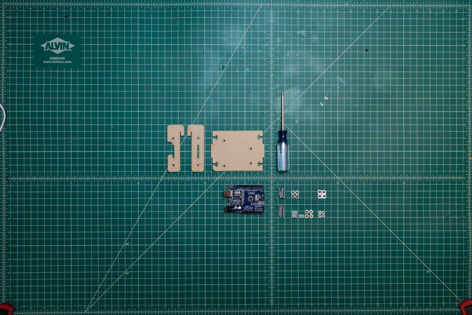 For the microcontroller you will need:
- Arduino Uno compatible microcontroller
- 4x #6-32 1/2” screws
- 4x #6-32 square nuts
- 4x #6 washers
- 4x #4-32 3/4” screws
- 4x #4-32 nuts
- 4x #4 washers
- 12x #4 1/8” spacers
- Base plate
- Side plate
- Side plate w/ cutout
- Phillips screwdriver
First, assemble the microcontroller mount chassis.
Then, Mount the arduino with the #4 hardware, with one spacer on top and two spacers underneath each mount hole.
Cables
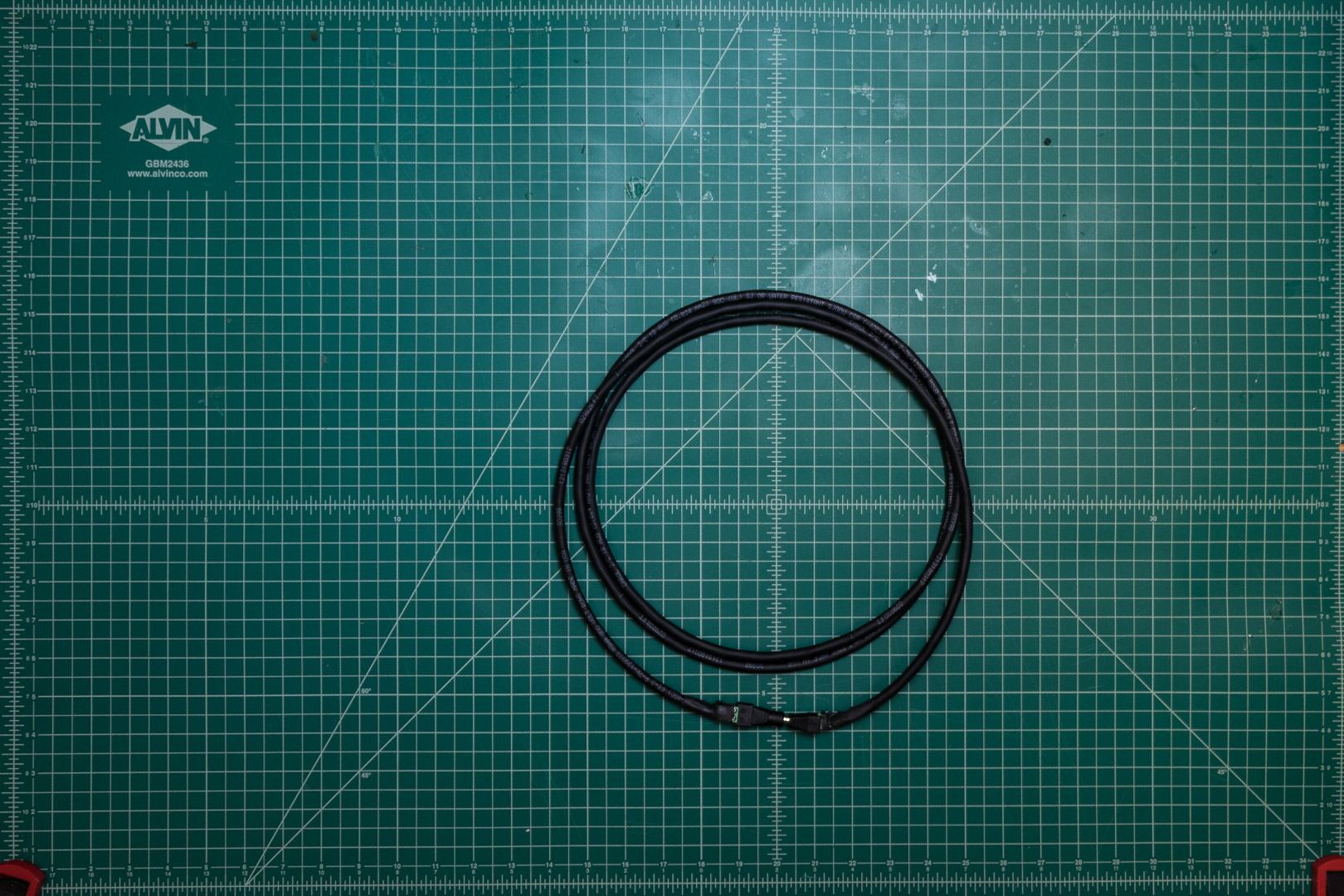
Power Cable
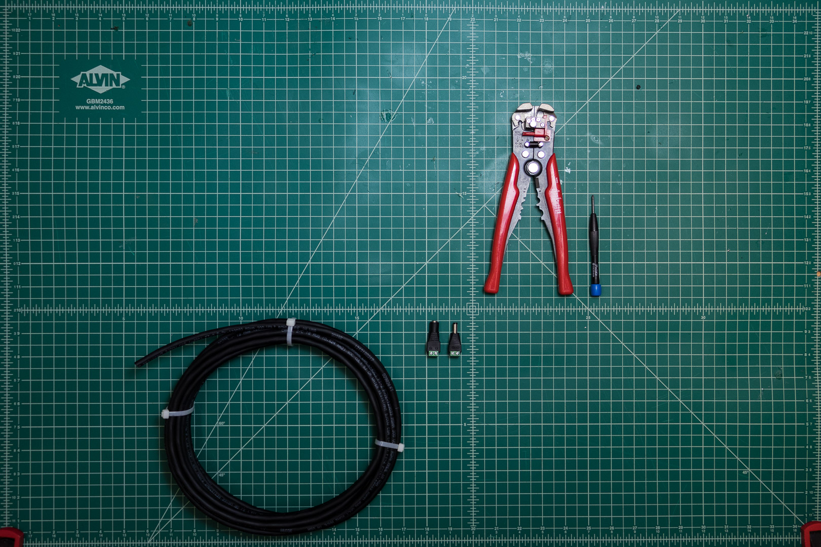 For the power cable, you will need:
- 2 conductor wire
- Male DC barrel jack
- Female DC barrel jack
- Wire strippers
- Small phillips screwdriver
Cut wire to desired length, then mount the barrel jacks on each side.
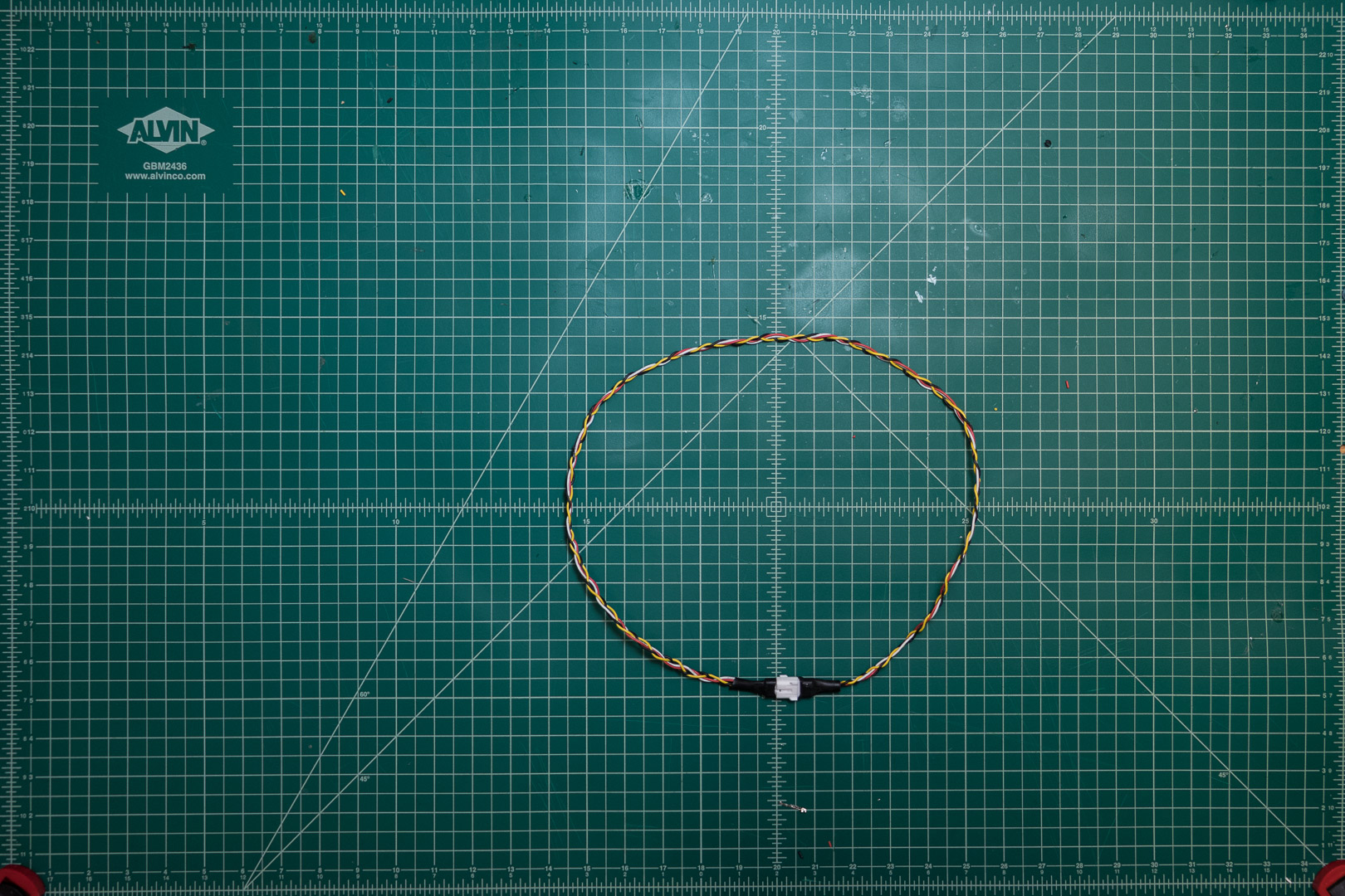
Servo Cable
For the servo cable, you will need:
- 3 conductor wire
- 6x Female crimps
- 2x 3 pin female 100 pitch header
- Wire strippers
- Crimpers
Cut 3 conductor wire to desired length, and then crimp female headers on either side.
Stepper cables
 For each stepper cable, you will need:
- 4 conductor wire
- 2x 4 conductor cable-to-cable connectors
- 8x matching crimps
- Wire strippers
- Crimpers
Cut 4 conductor wire to desired length, then crimp cable to cable connecters on either side.
Enjoy your BoardBot!